SpoolBuddy Assembly Guide
This guide walks you through assembling the SpoolBuddy from 3D-printed parts and electronics. Follow the steps in order — each section builds on the previous one.
Assembly Video
Prefer to watch instead of read? The full assembly walkthrough is available on YouTube:
Download Printed Parts
All parts are designed for SpoolBuddy and printed in PLA or PETG. Download the full project as a single .3mf file (recommended — all parts pre-arranged for slicing) or grab individual .stl files if you only need specific pieces. The editable .f3d Fusion 360 source is also available if you want to tweak the design.
SpoolBuddy.3mf — full project (all parts)
SpoolBuddy_V2.1.f3d — Fusion 360 source
| Part | File | Description |
|---|---|---|
| Case — Part 1 (Electronics) | case_part_1_electronics.stl | Electronics base — holds scale module, display rail guides |
| Case — Part 2 (Scale) | case_part_2_scale.stl | Scale housing — load cell channel, joins to Part 1 via dovetails |
| Case Cover | case_cover.stl | Lid for the scale housing (Case Part 2) |
| Case Back Cover | case_backcover.stl | Back cover for the main enclosure |
| Display Holder | display_holder.stl | Back bracket for the display, screws to case |
| Display Cover | display_cover.stl | Front bezel frame, clips over the display |
| NFC Reader Cover | nfc_reader_cover.stl | Cover for the PN5180 module on the spool plate underside |
| Spool Holder - 10mm Version | spool_holder.stl | Spool plate — mounts on load cell (10mm), holds filament spool |
| Spool Holder - 15mm Version | spool_holder_-_15mm.stl | Spool plate — mounts on load cell (15mm), holds filament spool |
| Spool Stopper | spool_stopper.stl | Curved arc, clips into spool plate rim |
Parts Inventory
Before starting, confirm you have all printed parts:
| Part | Qty | Notes |
|---|---|---|
| Case Part 1 — Electronics | 1 | Holds scale module, has display rail guides |
| Case Part 2 — Scale | 1 | Load cell channel, dovetail joins to Part 1 |
| Case Cover | 1 | Snaps onto Case Part 2 (scale housing) |
| Case Back Cover | 1 | Closes the back of the case, shared screws with display holder |
| Display Holder | 1 | Bracket screwed into display standoffs, slides into case rails |
| Display Front Cover Frame | 1 | Beveled bezel frame, clips over the front of the display |
| Spool Plate | 1 | Multiple hole positions for adjusting distance from display |
| Spool Stopper | 1 | Curved arc, clips into spool plate cutout |
| NFC Module Cover | 1 | Clips onto spool plate underside |
Hardware Required
| Screw | Qty | Used for |
|---|---|---|
| M4 × 25 mm hex socket | 4 | Load cell → Case Part 2 (2), Spool plate → load cell (2) |
| M3 × 5 mm self-tapping | 2 | Display assembly → case rail lock |
Before You Print — NFC Module Cover
Do this before printing the NFC Module Cover
The NFC Module Cover has a circular wire exit hole on the right side. If your NFC wiring requires a larger or differently shaped cutout, use a negative body/part in your slicer to enlarge it before printing. It is much easier to do this now than to modify a finished print.
Step 1 — Join Case Part 1 and Case Part 2
- Align the two dovetail joints on Case Part 1 (Electronics Base) and Case Part 2 (Scale Housing)
- Slide the two parts together until they are fully seated
- No screws are required — the dovetails hold the parts together firmly
- If you want extra rigidity, a small amount of superglue can be applied to the joint, but this is usually not necessary
Step 2 — Install the Scale Module (NAU7802)
- Place the NAU7802 PCB onto the 4 standoffs inside Case Part 1
- Press down until the board seats on all four standoffs
- Route the NAU7802 cables through the oval cable routing hole in the case wall
Step 3 — Mount the Load Cell
- Lower the load cell beam into the channel in Case Part 2 from above
- Secure it with 2x M4 × 25 mm hex socket screws through the top holes
- Route the load cell wires through the oval cutout on the side wall of Case Part 2
Step 4 — Fit the Case Cover
- Align the Case Cover over Case Part 2 with the open gap facing the front (towards the load cell beam)
- Press down until the two rear clips snap in and hold the lid in place
- The front gap is intentional — it allows the load cell beam to pass through freely
Step 5 — Display Sub-Assembly
LAFVIN display standoffs
The LAFVIN 7" HDMI Touch display comes with standoffs in the box. Use these to mount the Raspberry Pi — no separate standoffs are needed.
- Mount the Raspberry Pi onto the back of the display using the included standoffs
- Connect the HDMI and USB cables between the Pi and the display
- Attach the Display Holder to the back of the display — press it onto the display standoffs
- Press the Display Front Cover Frame onto the front of the display until the retention clip engages
Step 6 — Install Display Assembly into Case
- Tilt the display assembly at an angle and align it with the two sliding rail guides on Case Part 1
- Slide the assembly along the rails until it is fully seated
Step 7 — Install Case Back Cover
- Place the Case Back Cover against the back of the case, aligning it over the display holder
- Fasten the 2x M3 × 5 mm self-tapping screws into the Case Part 1 holes to lock the display assembly in place
Step 8 — Spool Plate Sub-Assembly
- Mount the PN5180 NFC module into the bracket on the underside of the spool plate
- Route the NFC cables through the wire cutout in the NFC Module Cover
- Clip the NFC Module Cover onto the underside bracket — it secures with side clips, no screws needed
Step 9 — Mount the Spool Plate
- Choose a screw hole position on the spool plate based on how far you want it from the display
- Lower the spool plate onto the load cell, aligning the chosen hole with the load cell mounting point
- Secure with 2x M4 × 25 mm hex socket screws from the top
Step 10 — Attach the Spool Stopper
- Align the curved spool stopper arc with the cutout on the spool plate rim
- Press/clip it into place — no screws needed
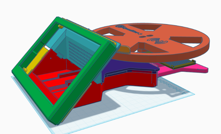
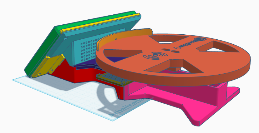
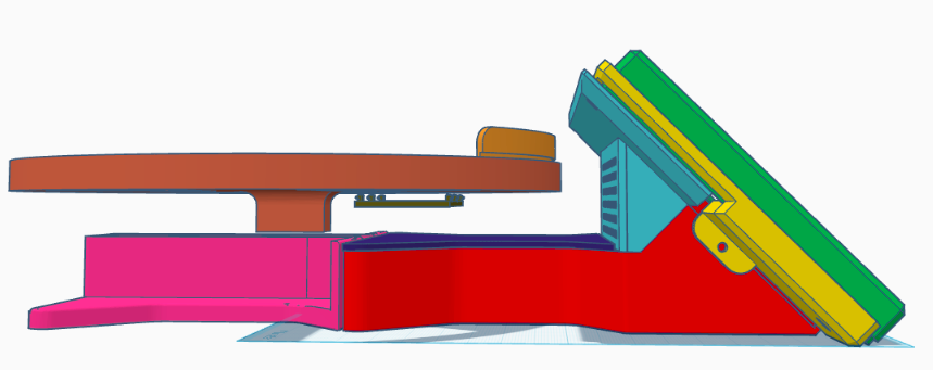
Assembly Complete
Your SpoolBuddy is now fully assembled. Before powering on:
- Check all screw connections are snug
- Confirm the load cell beam moves freely through the case lid gap
- Verify NFC module cables are routed and not pinched
- Plug in the angled USB-C connector to the Pi's USB-C port — the cable exits through the cutout on the back of the case
Proceed to the Installation guide to set up the software.